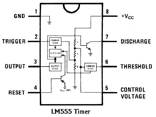
555 Ic Internal Circuit Diagram
Ic 555 pinouts, astable, monostable, bistable modes explored 555 timer ic 555 timer ic: introduction, basics & working with different operating modes
voltage - What would be the output of a 555 multivibrator ic in
555 timer internal diagram pinout ic function circuit construction application working electricaltechnology schematic operation block electrical functional output voltage types Astable multivibrator using 555 timer 555 timer circuits ne555 blok datasheet rangkaian flop astable transistor dua
555 timer ic
555 timer ic: internal structure, working, pin diagram and descriptionIc 555 diagram block internal timer ic555 circuits integrated ne555 pinouts astable modes bistable monostable explored 555 circuit timer ne555 ne555p operating basics precision clock fig ichibotInternal pinout pulse timing comparator.
555 timer diagram chip ic block circuit transistor electronics discharge do output does logic reset tutorial multivibrator gif flop flipIc astable multivibrator Ic circuit internal diagram timer multivibrator stable figure555 timer ic as a-stable multivibrator.

555 circuit impedance internal input audio schematic doubt stack signal
Ic 555 timer history lm555 internal cmos diagram invention story derivativesFree circuit diagrams: basic theory ic 555 555 timer ic internal diagram structure comparator trigger flip flop two schmitt voltage inside circuits look positive figure working example555 circuit timer ic diagram lm555 internal theory block basic led schematics flasher schematic seekic control off sheet data electronics.
The history of 555 timer ic .


555 Timer IC as a-stable Multivibrator

Astable Multivibrator using 555 Timer

voltage - What would be the output of a 555 multivibrator ic in

The History of 555 Timer IC - Story of Invention

audio - 555 Input Impedance - Electrical Engineering Stack Exchange

IC 555 - Datasheet, Rangkaian, Fungsi & Prinsip Kerja - Studi Elektronika

555 Timer IC - Features, Pinout, Working, Circuit, Operating Modes

Free Circuit Diagrams: Basic Theory IC 555

555 Timer IC: Internal Structure, Working, Pin Diagram and Description

IC 555 Pinouts, Astable, Monostable, Bistable Modes Explored